Share
Pin
Tweet
Send
Share
Send
Now many speakers are sold that have a card reader. You can install a memory card or USB flash drive. This is certainly great, but if someone wants to listen to music from their phone? You need to pull out the card and insert it into the card reader. Inconvenient after all. I decided to go the other way. I ordered a Bluetooth module in China. Called BK8000L. It is very convenient, has many functions. One drawback is very small. Well, nothing, we can handle it.
Will need
For the case I need plastic. I have deposits.

I cut out several blanks from plastic. A pair with dimensions 5 * 10 cm and a pair with dimensions 3 * 5 cm. I will cut out the rest of the pair later.

To output the audio signal, I will use two different sockets. One "tulip" type connector cut from a large block.

The second jack is like on headphones, with a size of 3.5 mm.

To connect an external power supply, I will install a 5.5x2.1 mm jack.

To turn off the device you need a switch. Applied from an old lamp.

Here is the module itself. Compact and functional.

I almost missed to describe the main thing. The device has autonomous power, yes. I will feed from a pair of Li-ion batteries, with an approximate capacity of almost 4.5 Ah.

I will charge the controller from China. I have a board without protection. I applied a separate BMS board.

Bluetooth receiver assembly
We proceed to the assembly of the box. In one blank I make a cut for the "tulip" connectors and the connector as on the headphones.

In the second blank I make a window for the power and charging connector.

Now you can glue our blanks. It turned out something like this. I attach the "tulip" connectors with super glue and soda. I try on a 3.5 mm connector.
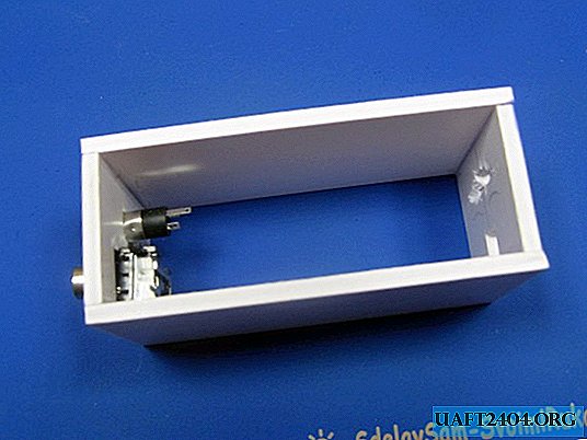
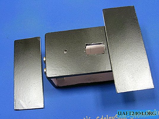
Cut a window under the switch. Cut the side blanks. Installed them temporarily and painted the body.
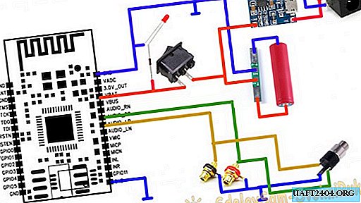
A few words about the scheme, on which everything is clear already. The circuit is basically available on the Internet. An external source is connected to the connector in the upper right corner, or you can connect micro USB charging to the controller. The power is supplied to the battery and fed through the switch to the module. The output signal is fed to the output connectors. Be it a tulip or a 3.5 mm jack. Plus in the diagram is red, minus respectively blue. We solder according to the scheme, everything is simple here. I also installed the LED. To indicate power on.
The controller was soldered to the battery. To the controller a connector for the PSU. At the same time, I soldered the output connectors.

I glue the batteries, the charge controller board and the bluetooth module on thermo glue. I solder wires to the switch.


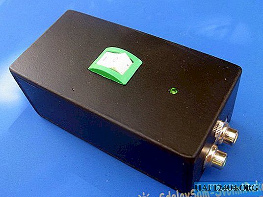
Everything is going to be very simple. If you own a soldering iron, then it will not be difficult to assemble this design. I glue the side blanks. This is what the finished design looks like. Everything works perfectly. Connected to a makeshift amplifier and to system 2.1.
Share
Pin
Tweet
Send
Share
Send