Share
Pin
Tweet
Send
Share
Send
Despite the abundance of powerful microcircuit and transistor sound amplifiers, there is always a need to have a small portable stereo amplifier that does not require powerful power. Just this can be built on the chip TDA1517P, its other name is YD1517P. The index “P” at the end means that the chip has a DIP 8 housing. Also, this chip is available in the SIL9MPF package, which provides for the installation of a radiator, in which case it is called TDA1517.
On AliExpress, such a chip costs a penny - TDA1517P.
Scheme

The TDA1517P connection diagram is extremely simple and contains only the minimum necessary binding. Capacitors C1 and C2 are loop-through, the larger their capacity, the more low frequencies will be at the output of the amplifier. Capacitors C4, C5 are also pass-through, serve to cut off the constant component of the signal, their capacitance can vary within 470-1000 microfarads. C6, C7 - capacitors-power filters. All electrolytic capacitors should be taken at a voltage of at least 25 volts. The optimal supply voltage of the circuit is 9-12 volts, while the output power is 5 watts per channel, which is enough to sound a small room. R1 - volume control potentiometer, you can use any dual 50 kOhm or 100 kOhm with a linear or logarithmic characteristic.

S1 - mono / stereo mode switch, needed in cases when only one channel receives a signal from the circuit input, for example, from old cassette players, radios. With the closed position S1, the signal “bifurcates” and both speakers play, even if a mono signal is input.
You can download the board and circuit here:
portativnyj-usilitel-s-mono-rezhimom-na-tda1517p-otpr.zip 76.53 Kb (downloads: 167)
Amplifier assembly
As always, the assembly begins with the manufacture of a printed circuit board, the figure of which is attached to the article. The board is made by the LUT method, the drawing is ready for printing and you do not need to mirror it.


After the board is etched and tinned, we solder the parts on it - first of all, resistors, a diode, a microcircuit, then massive capacitors. Last of all, we solder the controls on the wires to the board - toggle switches, a variable volume resistor, a terminal block for connecting speakers, a sound input jack, an LED, a power jack. I also installed an additional jack 6.3 jack, which is connected in parallel with the main jack 3.5. Plus, from the power connector, it goes first to the on / off switch, and only then to the board. The second toggle switch is a mono / stereo switch. When the soldering is completed, we remove the flux residues from the board and check for breaks or short circuits of the tracks.


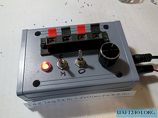
Installation in the housing
The board can be placed in any size-appropriate case. If the case is metal, then you should connect it with the minus of the circuit, protection from external interference will appear. I chose a small plastic case with dimensions of 100 x 70 x 35 mm.

When drilling holes, you should consider the dimensions of the components that are located inside, as well as the diameter of the holes for installing parts. Connect all the details, especially the audio input jack and the volume potentiometer, with the shortest possible wires, otherwise a background may occur. The board can be fixed to the case using racks with screws, or glue.


First turn on and listen
After the amplifier is assembled, you can begin to test. We connect the power supply of 9-12 volts, turning on the ammeter in series with it. We turn on the amplifier with a toggle switch, the ammeter should show a quiescent current of 40-80 mA, the LED will light up. Now you can connect the signal source, for example, a player, computer, phone, speakers to the terminal block and turn on the music. In the process, especially at high volume, the TDA1517P chip body can heat up to 40-50 degrees, this is normal. To power the amplifier, you can use any household power supply for 9-12 volts with a current of at least 500 mA. Successful assembly.

Share
Pin
Tweet
Send
Share
Send