Share
Pin
Tweet
Send
Share
Send
Not so long ago, this miracle of Chinese industry came into our life, but immediately won hearts with its simplicity and cheapness. And its simplicity lies in the following: bought a call, turned it on, threw it on a cabinet, glued a button at the door. Everything, no wires there for you, drilling holes for fastenings, etc ...
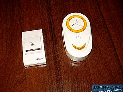
But still, let's look into it and look at the circuit diagram.
Button. Three transistors, 12 volt battery. The high-frequency generator is assembled according to a three-point capacitive circuit, an amplifier-converter. Converts from a frequency of the order of 433 MHz. What surprised me was the parallel inclusion of two circuits, one tuned to the primary frequency of the generator, and the second catches somewhere 10 harmonics and is excited at a frequency of 433 MHz. Our Chinese friends again found an original, and most importantly, simple solution to the problem using a minimum of detail.
The most interesting thing is that the transmitter does not have a transmitting antenna, of course it is inside, i.e. the circuit itself is to her. Thanks to the use of ultra-ultra-short-wave range this is enough.


The call. The receiver is assembled on a single transistor according to the regenerative detector circuit. The signal received from it is fed to the operational amplifier. Next, the signal enters the SOUND CHIP. It is not difficult to guess that he is the creator of the melodies that we hear. From it to a power amplifier assembled on a single transistor, and into a dynamic head. That's all, I just want to note a relatively small current consumption in standby mode.


Dismantled, looked, dismantled the work. All? No, not all! The bell is an almost universal transmitter-receiver circuit. Based on it, you can collect many other interesting devices.
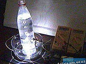
As an example. The bell controls the light.
We take our call and connect the circuit, which is shown below.

This is a normal trigger. When a pulse arrives at him from a call, he switches to one of the fixed positions. The trigger has a relay at the output, and a controlled device is connected to the relay, in our case it is an incandescent lamp.

An example of the location of the bell and the button.

Printed circuit board.
The location of parts on the circuit board.

PS: I was tormented by the question: where to get food for this circuit? Not a separate line to lead? That's where you can find a way out so it is in dual wiring. If your wiring in the ceiling is designed for two lamps, and at the switch two buttons the answer came by itself - the device controls one button, and the second one is powered, say, by charging from a mobile phone (it is economical).
Share
Pin
Tweet
Send
Share
Send