Share
Pin
Tweet
Send
Share
Send
Gas-discharge indicators have long sunk into oblivion; personally, they are even the most “newer” ones to me. GRI was used mainly in watches and measuring instruments, later vacuum-luminescent indicators came in their place.
So what is a GRI lamp? This is a glass bottle (it's a lamp!) Inside filled with neon with a small amount of mercury. Inside, electrodes bent in the form of numbers or signs are also located. It is interesting that the symbols are arranged one after another, therefore, each symbol glows at its depth. If there are cathodes, there must be an anode! - he is one at all. So, in order to ignite a certain symbol in the indicator, you need to apply voltage, and not small, between the anode and cathode of the corresponding symbol.
For reference, I would like to write how the glow occurs. When a high voltage is applied between the anode and cathode, the gas in the lamp, which was previously neutral, begins to ionize (i.e., a positive ion and an electron are formed from a neutral atom). The positive ions formed begin to move toward the cathode, the released electrons, toward the anode. In this case, the electrons "along the way" additionally ionize the gas atoms they encounter. As a result, an avalanche-like process of ionization occurs and an electric current appears in the lamp (glow discharge). So now the most interesting, in addition to the ionization process, i.e. the formation of a positive ion and electron, there is an inverse process, they call it recombination. When a positive ion and electron "turn" again into one! In this case, energy is released in the form of a glow, which we observe.
Now directly to the clock. Lamps I used IN-12A. They have a not quite classic lamp shape and contain the characters 0-9.
I bought a fair amount of lamps that were not in use!
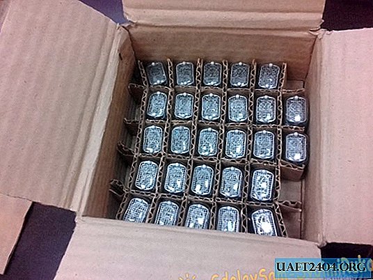
So to say, enough for everyone!
It was interesting to make a miniature device. The result is a fairly compact product.
The case was cut out of black acrylic on a laser machine according to the 3D model, which was made based on printed circuit boards:


Device diagram.
The watch consists of two boards. On the first board there are four IN-12A lamps, a K155ID1 decoder and optocouplers for controlling the anodes of the lamps.

The board also has inputs for connecting power, controlling optocouplers and a decoder.
The second board is the brain of the watch. It contains a microcontroller, a real-time clock, a 9V to 12V conversion unit, a 9V to 5V conversion unit, two control buttons, a beeper and the outputs of all signal wires that match the display board. The real-time clock has a backup battery, which does not allow time to be lost when the main power is turned off. Power is supplied from a 220V-9V unit (200mA is enough).

General view of boards:


These boards are connected using a pin connector, but not with an insert, but with soldering!


This whole thing is going this way. First, a long screw M3 * 40. A tube from a 4mm air hose is put on this screw (it is tight, and is suitable for holding printed circuit boards, I use it very often). Then, between the printed circuit boards, a stand (printed on a 3D printer) and then a brass through nut tightens all this. And the back wall will also be fastened with M3 bolts to the through brass nuts.


When assembling it turned out such an unpleasant feature. I wrote the firmware, but the clock refused to work, the lamps flickered in an incomprehensible order. The problem was solved by installing an additional capacitor between + 5V and ground right next to the microcontroller. It can be seen in the photo above (installed it in the programming slot).
I attach the project files in the EagleCAD program and the firmware in CodeVisionAVR. You can upgrade if necessary for your own purposes)))
The firmware of the watch is made quite simple without bells and whistles! Just a watch. Two control buttons. One button is “mode”, the second is “setting”. By pressing the "mode" button for the first time, only the numbers that are responsible for the clock are displayed; if in this mode you press the "setting", the clock will start to increase (when it reaches 23, it will reset to 00). If you click on "mode" again, only minutes will be displayed. Accordingly, if you press "setup" in this mode, the minutes will also increase in a "circular" order. With one more press on "mode" - both hours and minutes are displayed. When changing hours and minutes, seconds are reset to zero.


In future versions, I think, make three buttons and make the inscription engraved.
Project files are available only for registered users:
Attention! You do not have permission to view hidden text.
Share
Pin
Tweet
Send
Share
Send