Share
Pin
Tweet
Send
Share
Send
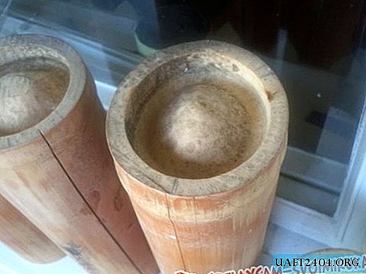
The OHP-10 fire extinguisher was produced as a receiver, with a declared volume of 8.7 liters, actually measured and amounting to 10.5 liters. A fire extinguisher gained internship at the enterprise. He simply went to the head of the fire safety department or xs as he is called, and asked if there was a decommissioned fire extinguisher. Gave him.
I must say right away, do not try to release its contents in the bathroom. While I was dragging him to the house, I went behind the garages and released there (it will bring a lot of childish pleasure;). a PM5 pressure switch was also purchased, designed for water, but suitable for air. I also bought two dehumidifier filters, and one automobile fuel one, of fine cleaning (I immediately put it on the compressor inlet.
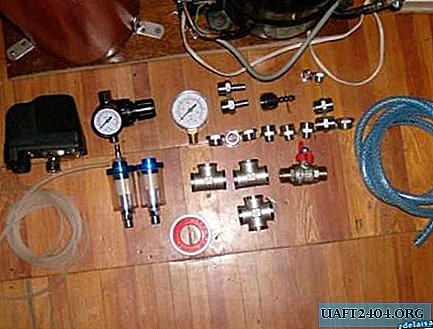
I bought all sorts of adapters, crosspieces, also a reinforced PVC hose with an internal diameter of 10 mm. All that was included in the set, see the photo. I also acquired a valve (at first I thought that I would regulate the pressure, and that it was no different from the gearbox (naive).
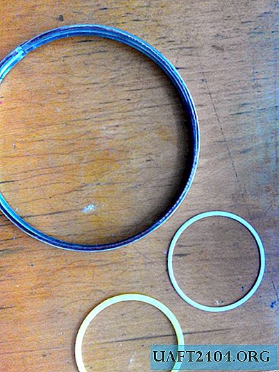
After I figured out that the valve and the gearbox were all slightly different, I bought a gearbox with a pressure gauge, and a separate pressure gauge to measure the pressure inside the receiver. They also bought a thin hose xs what diameter, in a pet shop, costing as much as 10 rubles / meter :))). It is either silicone, or some kind of xs, but very flexible, lightweight and durable, there is nothing better for supplying an airbrush.
Well, of course, the same thing without the FUM tape, which is sold in any plumbing store.
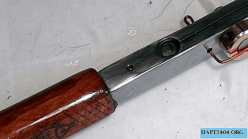
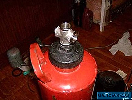
First of all, we screw the balloon to the base (I think you’ll figure it out yourself, there are no tricks here). We take out all the goodness from the lid, and from the inside of the fire extinguisher, we leave only the cylinder itself and the lid.

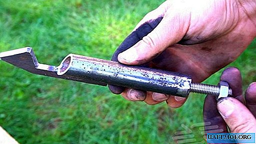
In the hole in the cast-iron lid we cut the pipe thread, 1/4 inch. Also, we wind the FUM tape on a wide thread on the balloon, make a rubber gasket (in theory it should be, I had it, but I did it somewhere, and as a result I cut it out of the camera for a car, after construction I found my own))) ) and screw on the cast iron cover.
Screw the adapter from 1 / 4HP to 1 / 2HP inches into the hole in the lid.
Next, we screw a 1/2 inch cross (I will simply write 1/2 further), of course, all connections to the FUM tape, I will not mention this anymore.
Screw the pressure switch into the crosspiece through the adapter 1 / 2НР-1 / 4НР, screw the adapter 1 / 2НР-1 / 2НР from the side.

Next, screw the tee on the side.

On one side, we fasten to it a reducer with a 1 / 4HP thread through an adapter 1 / 2HP-1 / 4BP.

From the other end, also through the adapter 1 / 2НР-1 / 4ВН, screw a manometer with a thread of 1 / 4НР. On the opposite side of the cross, we screw in the valve (for bleeding air from the cylinder), which has a 1 / 2HP thread.

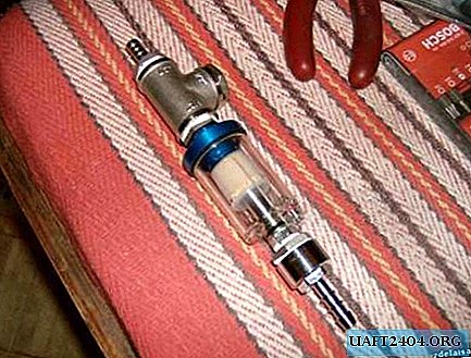
We screw the filter-water separator to the gearbox, which has a 1 / 4HP thread and goes straight to the gearbox. Here, the fact is that the filter should stand correctly (observe the top and bottom), and make sure that the drain hole is at the lowest point.

Next, we draw up the line of another filter, from the inlet side there is a 1 / 2ВР fitting, which is connected through the 1 / 2НР-1 / 4ВР adapter, we screw it onto the filter having a 1 / 4НР thread. From the outlet, I was a little powdered, because there were extra parts, and there weren’t some necessary ones, in the end it turned out like this.
An adapter 1 / 4НР-1 / 2НР is screwed into the hole in the 1 / 4ВР filter, a tee is screwed to it (here I had one, I had one), on one side of which a plug with 1 / 2НР is screwed, on the other side of the tee, a fitting is screwed on to the filter 1/2 HP
ATTENTION: I did it so surprisingly because there were unnecessary details so that you would not make this mistake, do so, the adapter 1 / 4НР-1 / 2НР is screwed into the outlet, and the fitting for the hose with a 1 / 2ВР thread is screwed onto it. The layout below will be given for this particular option.
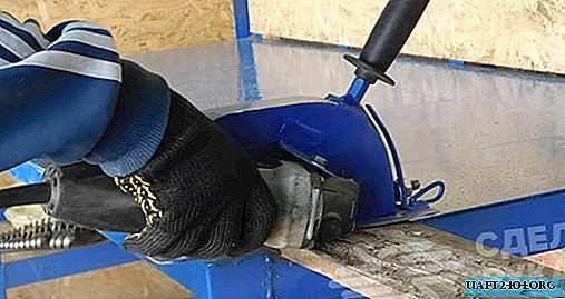
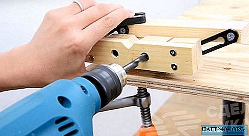
Further, to the hole with an external thread of incomprehensible cross-section and step (I could not find) that comes out of the fire extinguisher as an output nozzle, a reinforced hose is ideally suited, which we fix with a clamp on top.
From the other end of the hose we insert the fitting from the filter and also fix it with a clamp.

Next, from the inlet filter nozzle, we again insert the reinforced sling and bring it already to the compressor outlet pipe. how to fix this good there, I think you’ll come up with. I have a cunning system of several gaskets there and everything is clamped on top with a clamp.

In conclusion, we screw a 1/4 НР fitting into the outlet of the 1 / 4ВР filter, onto which we mount a silicone tube that sits almost perfectly on it, and does not even require crimping with a clamp, the other end of the tube is already to the airbrush.
Since the pressure after the pressure reducer is small compared to the receiver, the tube can withstand it without any effort. At the entrance to the compressor, as I already said, a car filter is installed to clean the air. Oil…
Regarding the oil change, three pipes come out of the compressor. one input, another output, the third sealed, and is for adding oil. Here we are tearing it (I just had a bite with pliers), but look so that the sawdust does not get inside, otherwise the motor may be over.
From there we drain the oil. How much leaked, I honestly did not measure, but something about a glass. I poured in an automobile oil of formula 10W40, with a volume of about 350 grams. IMHO, automobile oil is better in that, firstly, it has a bunch of additives that protect against any threshing floor, and secondly, unlike spindle oil, it does not "absorb" moisture.
Author: Roman Vetrov
Sources: SdelayKompressor.ru
Share
Pin
Tweet
Send
Share
Send